
Introduction
In the electronics manufacturing industry, reflow oven soldering is a critical step in achieving high-quality SMT assembly. As electronic products continue to evolve toward higher performance, miniaturization, and higher density, the requirements for soldering in SMT production lines are also increasing.
This article will start from the basic principles of reflow soldering to explain how to scientifically and reasonably optimize the reflow soldering process, helping to improve product yield, reduce rework costs, and enhance production efficiency.
I. Overview of the Reflow Soldering Process
1. Definition of Reflow Soldering Machine
Reflow soldering is a technology that melts solder paste through heating and then cools and solidifies it to achieve electrical connections and mechanical fixation between components and PCBs. Its core process includes four stages: preheating, temperature stabilization, reflow, and cooling.
2. Overview of Reflow Soldering Structure
Modern reflow soldering ovens typically use a multi-zone design, with common configurations ranging from 6 to 12 temperature zones.
NeoDen Reflow Oven
NeoDen IN6, NeoDen IN12, NeoDen IN12C, NeoDen IN8C, NeoDen T Series
Depending on the heating method, they can be categorized into infrared heating, hot air heating, and infrared + hot air hybrid heating, among other types.
II. Analysis of Key Parameters in the Reflow Soldering Process
1. Temperature Profile
The temperature profile is one of the core parameters in the reflow soldering process and directly impacts solder joint quality.
- Preheating Stage: Slowly increase the temperature to avoid thermal shock.
- Temperature Holding Stage: Ensure uniform temperature across all PCB areas.
- Reflow Stage: The peak temperature must exceed the solder paste melting point (typically above 217°C), but should not be excessively high to prevent component damage.
- Cooling stage: Rapid cooling helps form a good crystal structure and enhances joint strength.
2. Solder Paste Characteristics
The composition, particle size, and flux content of solder paste all affect soldering performance. For example, SAC305 is the most commonly used lead-free solder paste, offering excellent wettability and mechanical properties.
3. PCB Design and Layout
- Component Arrangement: When mixing large and small components, consider thermal capacity differences to prevent the “shadow effect”.
- Pad design: Ensure pad dimensions match component leads.
- Through-hole/blind/buried via placement: Avoid proximity to pads to prevent bubbles or cold solder joints.
4. Oven Atmosphere Control
Nitrogen-protected reflow soldering (N₂ Reflow) effectively reduces oxidation and improves wettability, particularly suitable for high-reliability products. However, it also increases operational costs, requiring a balance of benefits and drawbacks.
III. Common Soldering Defects and Causes Analysis
| Defect Type | Cause Analysis | Improvement Recommendations |
| Cold Solder Joint | Insufficient preheating, peak temperature too low, poor solder paste printing | Check temperature curve, optimize printing parameters |
| Solder Balls | Flux splatter, insufficient drying before reflow, template openings too large | Control preheating time, adjust template design |
| Tombstoning | Uneven heating at both ends of the component, asymmetric solder paste volume | Optimize PCB layout, balance pad thermal capacity |
| Solder Bridging | Solder paste printing offset, excessive reflow temperature | Calibrate the printer, adjust the reflow curve |
| Non-Wetting | Pad oxidation, solder paste aging, insufficient nitrogen concentration | Strengthen incoming material inspection, replace solder paste batches |
IV. Reflow Soldering Process Optimization Flowchart
1. Set a scientific SMT processing reflow soldering temperature curve and conduct real-time temperature curve testing on a regular basis.
2. Solder according to the soldering direction specified in the PCB design.
3. Prevent conveyor belt vibration during soldering.
4. Inspect the soldering quality of the first printed circuit board.
5. Check for adequate soldering, smooth solder joint surfaces, semi-circular solder joint shapes, solder balls and residues, and solder bridges or cold solder joints. Also inspect for changes in PCB surface color. Adjust the temperature curve based on inspection results. Conduct regular quality checks throughout the production batch.
6. Regular maintenance of the reflow soldering machine is required. Due to prolonged operation, organic or inorganic contaminants such as resin may accumulate and solidify on the machine. To prevent secondary contamination of the PCB and ensure smooth process implementation, regular maintenance and cleaning are necessary.
7. Validation and Standardization
After optimization, conduct batch trial production verification, collect data on first-pass yield rates, SMT AOI equipment inspection results, and SMT X-ray equipment inspection data, and establish standard operating procedures (SOPs). Regularly conduct process reviews and retraining.
V. Practical Case Sharing
Case 1: Optimization of Soldering Issues in a Communication Module
Problem Description
The customer reported intermittent circuit breaks in a communication module. Upon disassembly, extensive soldering defects were found.
Cause Analysis
- The solder paste batch used was outdated, resulting in reduced flux activity.
- The temperature in the heat preservation segment of the reflow soldering curve was too low, preventing the solder paste from fully activating.
- Large areas of copper foil on the PCB caused rapid heat dissipation, leading to localized temperature drops.
Optimization Measures
- Replace with fresh solder paste.
- Increase the heat preservation segment temperature to 150°C.
- Add thermal compensation design near the copper foil.
- Add nitrogen protection.
Effect verification
After optimization, the first-pass rate increased from 82% to 98%, and customer complaints dropped to zero.
Case 2: LED strip solder ball issue resolution
Issue description
LED strips exhibited a large number of solder balls after reflow soldering, affecting appearance and subsequent packaging.
Root cause
- Too rapid temperature rise during the preheating stage of reflow soldering, resulting in incomplete evaporation of the flux.
- The stencil opening was slightly larger than the pad, leading to excessive solder paste volume.
Solutions
- Slow down the temperature rise rate and extend the preheating time.
- Adjust the stencil opening ratio to 90% of the pad area.
- Add a cleaning process.
Results
The number of solder balls decreased by over 90%, and customer acceptance significantly improved.
VI. Future Trends and New Technology Outlook
With the development of smart manufacturing, the reflow soldering process will also continue to evolve:
1. Intelligent reflow soldering systems
Reflow soldering equipment integrated with AI algorithms can automatically identify product features, dynamically adjust temperature curves, and achieve unmanned operation and predictive maintenance.
2. Application of digital twin technology
By constructing a virtual production line model, the soldering process can be simulated in advance to predict potential risks and shorten the debugging cycle.
3. Research and Development of New Solder Paste Materials
The application of new materials such as nano-solder paste and low-temperature alloy solder paste can help address challenges in welding high-temperature-sensitive components.
Conclusion
As a core process in the SMT production line, reflow soldering process optimization not only impacts product electrical performance and reliability but also directly influences a company's production efficiency and market competitiveness. Through scientific data analysis, systematic optimization processes, and continuous quality improvements, we can refine the reflow soldering process to its fullest potential.
We hope this article provides valuable insights to help your team achieve greater stability and success in the electronics manufacturing field. If you are interested in SMT production lines, please feel free to contact us.

Quick facts about NeoDen
1. Established in 2010, 200 + employees, 27000+ Sq.m. factory.
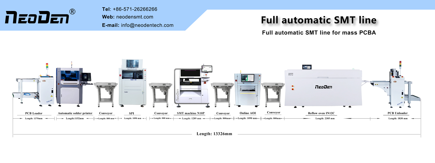
2. NeoDen Products:Different Series SMT machines, NeoDen YY1, NeoDen4, NeoDen5, NeoDen K1830, NeoDen9, NeoDen N10P; Reflow Oven IN Series, as well as complete SMT Line includes all necessary SMT equipment.
3. Successful 10000+ customers across the globe.
4. 40+ Global Agents covered in Asia, Europe, America, Oceania and Africa.
5. R&D Center: 3 R&D departments with 25+ professional R&D engineers.
6. Listed with CE and got 70+ patents.
7. 30+ quality control and technical support engineers, 15+ senior international sales, for timely customer responding within 8 hours, and professional solutions providing within 24 hours.
Post time: Jun-06-2025