
To understand the challenges brought by miniaturized components to solder paste printing, we must first understand the area ratio of stencil printing (Area Ratio).
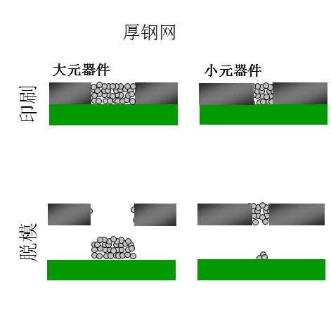
For the solder paste printing of miniaturized pads, the smaller the pad and the stencil opening, the more difficult it is for the solder paste to separate from the stencil hole wall.To solve the solder paste printing of miniaturized pads, there are the following solutions for reference:
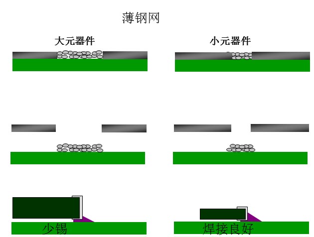
- The most direct solution is to reduce the thickness of the steel mesh and increase the area ratio of openings.As shown in the figure below, after using a thin steel mesh, the soldering of the pads of small components is good. If the substrate produced does not have large-size components, then this is the simplest and most effective solution. But if there are large components on the substrate, the large components will be poorly soldered because of the small amount of tin. So if it is a high-mix substrate with large components, we need other solutions listed below.
- Use the new steel mesh technology to reduce the requirement for the ratio of openings in the stencil.
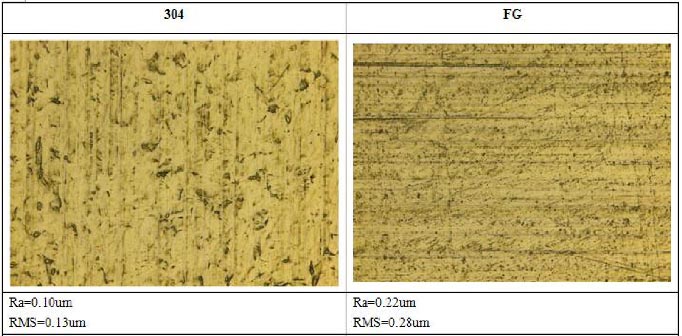
1) FG (Fine Grain) steel stencil
FG steel sheet contains a kind of niobium element, which can refine the grain and reduce the overheat sensitivity and temper brittleness of steel, and improve the strength. The hole wall of laser-cut FG steel sheet is cleaner and smoother than that of ordinary 304 steel sheet, which is more conducive to demolding. The opening area ratio of the steel mesh made of FG steel sheet can be lower than 0.65. Compared with the 304 steel mesh with the same opening ratio, the FG steel mesh can be made slightly thicker than the 304 steel mesh, thereby reducing the risk of less tin for large components .
Post time: Aug-05-2020