



Introduction
In today's highly homogeneous hardware circuit landscape, the firmware programs embedded in microcontrollers, programmable logic devices, and various SoC chips directly determine the final functionality and core performance of electronic products. Given the extremely rapid iteration cycles of IoT devices, automotive electronics, and industrial control boards, a single physical hardware model often corresponds to several or even dozens of different software versions across different production batches. In the high-speed PCBA manufacturing process, version mix-ups, incorrect programming, or missed programming during the firmware programming stage can have devastating consequences for quality. This is because such software-level defects cannot be identified through conventional in-line optical inspections such as SPI or AOI. The introduction of a firmware version barcode verification system-which implements closed-loop calibration at the underlying data level between the software package version and the physical board's unique UID-serves as the foundational process barrier for achieving zero-defect delivery.
Quality Characteristics of Incorrect Firmware Versions and Blind Spots in Traditional Control
In the high-speed post-SMT processes, the programming of the main control chip is typically divided into offline programming and online board-level programming. Offline programming relies on operators to place bare chips into the programmer in advance and then transfer the chips to the assembly line after programming is complete. Under traditional management models, operators rely on filenames displayed on the programmer's software interface and manually applied color-coded labels to distinguish between versions. In a workshop environment characterized by mixed-line production of multiple product varieties and frequent changes to customized software requirements, this method-which relies on manual visual verification-harbors significant control vulnerabilities. If an operator selects the wrong suffix code or mixes finished programmed chips of different versions while changing component trays, the incorrect chips will naturally be mounted onto printed circuit boards and pass through the reflow soldering process. Since the chips look identical, if the test bench has not updated the corresponding communication protocol verification scripts, these semi-finished products with programming errors will proceed unchecked all the way to final packaging, resulting in catastrophic functional failures for end customers.
The Underlying Architecture and Hardware-Software Interlock Mechanism of the Firmware Version Barcode Verification System
To overcome the critical vulnerability of incorrect firmware version programming, it is essential to use digital machine language to forcibly block any path for manual intervention. The firmware version barcode verification system integrates programming equipment, the MES system, and scanning hardware into a unified, three-pronged material control network. The system establishes a rigorous firmware version database on the server side; each set of standard hexadecimal or binary program packages approved by R&D is automatically assigned a unique firmware version barcode. At the programming workstation during PCBA manufacturing, the system controls the programmer via a dedicated encrypted communication protocol. Before beginning work, operators must perform a mandatory dual-code verification procedure. First, they use a laser scanner to read the product UID on the production order and the serial number QR code on the circuit board itself; second, they scan the firmware version barcode affixed to the programmer or programming fixture.
Millisecond-Level Data Verification and Electrical Hard Interlock with the Programming Host
The deep integration of real-time data validation with hardware control execution is the core strength of this system in preventing incorrect programming. Once the two sets of barcode data are captured, the system's control kernel retrieves the standard BOM parameters for the current work order within milliseconds. Only when the model and batch associated with the board's UID match the scanned firmware version barcode 100% will the verification system send an unlock pulse signal to the programmer's main control board. At this point, the programmer's power circuit is energized, activating the VCC power supply and data transmission lines, thereby allowing erase, write, and verification operations to proceed. If, during production scheduling transitions, a materials handler inadvertently imports the previous generation's product program, the system will activate a hardware interlock the moment it detects the data mismatch. This immediately cuts off power to the programmer's channels, blocks the programming data bus, and displays a full-screen red warning on the tablet screen, accompanied by a continuous buzzer alarm. This physical mechanism completely prevents the erroneous program from being written to the chip.
Reverse Injection of Program Verification Codes and Full-Link Digital Twin Data Closed-Loop
A high-level firmware control solution must not only implement interception at the front end but also require that the software data status be permanently recorded in the product's digital archive upon completion of the programming. In the final second after the programming operation is complete, the programmer automatically reads the cyclic redundancy check (CRC) code or checksum from a specific flash memory address within the chip. The firmware version barcode verification system packages this real-time physical checksum-along with the device ID of the unit performing the burn-in, the operator ID, the timestamp, and the chip's unique internal serial number-and uploads it to the factory's MES database as the digital "birth certificate" for that PCBA. During the subsequent functional testing phase, the system uses a host computer to read the chip's software version number and performs a reverse comparison against this data set. Through this closed-loop, end-to-end digital data chain, companies can provide overseas customers with an absolute chain of evidence demonstrating the software compliance of every circuit board.
Digitally tracking the flow of every line of code and locking in the software version with microsecond-level precision represents an inevitable evolution toward greater rigor and precision in modern precision electronic assembly processes. Only by using technological means to guard against hidden risks can the quality foundation of cutting-edge manufacturing be truly demonstrated.
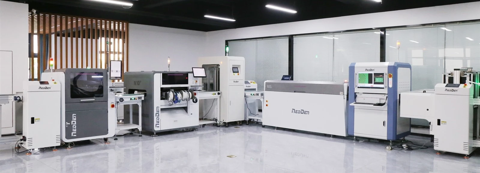
Quick facts about NeoDen
- Established in 2010 with 200+ employees & 27,000+ Sq.m. factory of independent property rights, to ensure the standard management and achieve the most economic effects as well as saving the cost.
- Owned the own machining center, skilled assembler, tester and QC engineers, to ensure the strong abilities for NeoDen machines manufacturing, quality and delivery.
- 40+ global partners covered in Asia, Europe, America, Oceania and Africa, to successfully serve 10000+ users in all of the world, to ensure the better and faster local service and prompt response.
- 3 different R&D teams with total 25+ professional R&D engineers, to ensure the better and more advanced developments and new innovation.
- Skilled and professional english support&service engineers, to ensure the prompt response within 8 hours, solution provides within 24 hours.
- The unique one among all of the Chinese manufacturers who registered and approved CE by TUV NORD.
- NeoDen supplies life-long technical support and service for all of the NeoDen machines, moreover, regular software updates based on the using experiences and actual daily request from the endusers.