



Introduction
In an SMT production line, the solder paste printer is the first step in the entire electronic assembly process. As a core piece of equipment preceding the component placement stage, its function is to precisely print solder paste onto the PCB surface according to the locations of the PCB pads.
Industry experience shows that the vast majority of soldering defects in the SMT assembly process-such as cold solder joints, solder bridges, and tombstoning-can be traced back to the front-end solder paste printing stage. Therefore, understanding the working principles of solder paste printers and mastering reasonable selection criteria are crucial for establishing a stable and efficient SMT production line.

What Does a Solder Paste Printer Do?
1. Its Core Role in the SMT Production Line
A typical SMT production process can be summarized as: Solder paste printing ➔ Component placement ➔ Reflow soldering ➔ Inspection.
Solder paste printing is not simply "brushing solder paste onto a PCB," but rather a precision process requiring the coordinated interaction of multiple parameters. To achieve high-quality transfer, the equipment must precisely control the following core actions:
- PCB and stencil alignment: Ensures consistent physical reference between the board and the stencil.
- Mark point recognition and correction: Corrects micron-level deviations via an optical system.
- Squeegee pressure and printing speed: Controls the flow and filling of solder paste within the stencil apertures.
- Discharge process and stencil cleaning: Ensures complete solder paste formation and no residue on the stencil's underside.
Taking the NeoDen ND450 fully automatic solder paste printer as an example, it integrates the above control processes into a unified software system via adjustable PCB tracks, a dual-camera vision system, a 3-axis adjustment platform, and an electro-pneumatic floating squeegee head, thereby achieving automated printing control.
2. Why does solder paste printing quality directly affect PCB soldering?
If defects occur during the printing stage, subsequent placement and reflow soldering processes often cannot correct them, directly leading to soldering failures. Common printing issues include:
- Solder paste misalignment: Causes solder bridges between pins or cold joints at one end.
- Insufficient coverage/insufficient solder: Results in weak solder joints or open circuits.
- Molding pull-out/collapse: Causes short circuits between adjacent pins.
- Insufficient PCB support: Causes board warping, resulting in uneven printing thickness.
To address the common issue of printing misalignment, the NeoDen ND450 is equipped with a 3-axis PCB adjustment platform and a high-precision magnetic scale feedback system. Combined with Mark Camera calibration, this setup minimizes soldering defects caused by mechanical or positional deviations at the source.
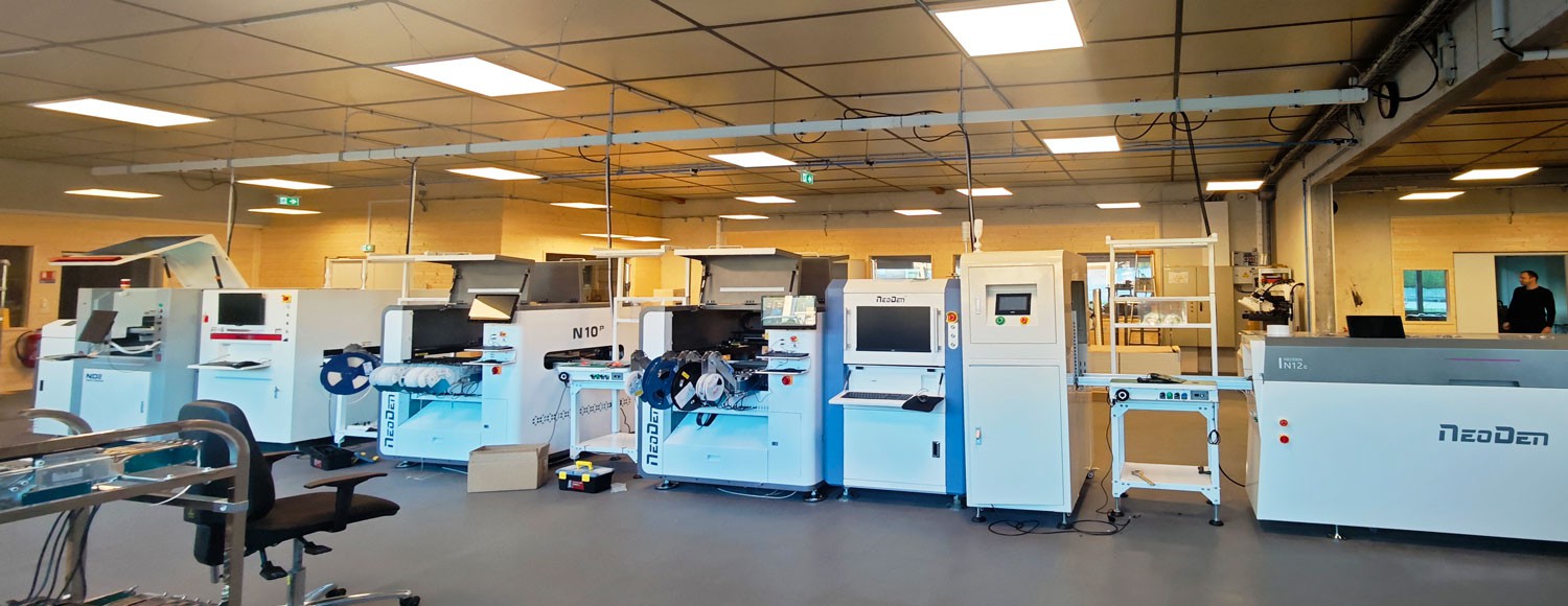
How does a solder paste printer work?
The operation of a fully automatic solder paste printer can be divided into four consecutive standard steps:
Step 1: PCB enters the conveyor and is positioned
The PCB enters the machine via the conveyor. At this point, the machine automatically adjusts the conveyor width, clamps the PCB's sides, and raises the support thimbles on the bottom.
Equipment Example: The ND450 features an adjustable lifting platform and a 45° guide rail design, enabling stable support for PCBs of varying thicknesses, with initial position calibration performed by a 3-axis platform.
Step 2: Visual Alignment of the PCB and Stencil
To eliminate manufacturing tolerances in the PCB and mechanical clamping errors, the equipment activates the Mark Camera recognition system:
- Upper and lower cameras scan the mark points on the PCB and the stencil, respectively.
- The image processing system calculates the relative positional deviation between the two.
- The 3-axis adjustment platform fine-tunes the PCB's position to achieve micron-level precision alignment.
Equipment Example: The ND450 is equipped with a dual-camera system (upper and lower) supplemented by a 6-channel adjustable lighting system, enabling it to adapt to the identification requirements of PCB surfaces with different materials, colors, and reflectivity levels.
Step 3: The squeegee pushes the solder paste through the stencil apertures
Once alignment is complete, the stencil is in close contact with the PCB. The squeegee head advances at a preset speed and pressure, causing the solder paste to roll across the stencil. During this process, shear forces cause the solder paste to flow and fill the stencil apertures.
Equipment Example: The ND450 employs an Electric + Air-Suspension Squeegee Head, which uses closed-loop pneumatic and electronic control circuits to maintain balanced squeegee pressure in real time, preventing stencil damage from excessive pressure or solder residue caused by insufficient pressure.
Step 4: Stencil Demolding and PCB Output
After printing is complete, the PCB lift platform descends vertically, separating the PCB pads from the stencil. The demolding speed and demolding distance directly determine the sharpness of the solder paste edges. Subsequently, the PCB is transferred to the next process, and the equipment initiates an automatic cleaning program for the underside of the stencil, depending on the settings.
What Core Parameters Should You Consider When Purchasing a Solder Paste Printer?
For procurement and technical personnel, we recommend focusing on the following six technical dimensions when evaluating a printer:
[ 1. PCB Size and Thickness ] ─── [ 2. Clamping and Support Structure ] ─── [ 3. Stencil Clamping Rigidity ]─── [ 4. Vision Alignment Accuracy ]─── [ 5. Squeegee and Parameter Adjustability ]─── [ 6. Automatic Cleaning Module ]
1. PCB Size and Thickness Compatibility Range
Evaluate whether the equipment's rail adjustment capabilities cover your current and future product lines, including maximum and minimum PCB dimensions, as well as compatibility with irregularly shaped, thick, or thin boards. The ND450's lift platform design seamlessly accommodates PCB specifications of varying thicknesses.
2. PCB Positioning and Clamping Methods
Insufficient clamping rigidity can cause board displacement during printing. In addition to side clamping, attention should be paid to the flexibility of the bottom thimble arrangement to prevent the PCB surface from sagging. The ND450 employs a lead screw/nut backlash elimination mechanism in conjunction with a 3-axis platform to ensure a smooth, gap-free clamping process.
3. Stability of the Stencil Mounting Structure
The rigidity of the stencil frame directly affects long-term repeatability in printing accuracy. The material of the crossbeam and the pneumatic locking mechanism must be evaluated. The ND450's stencil crossbeam is precision-machined via CNC, paired with high-precision linear guides on both sides and secured by dual pneumatic cylinders, ensuring no micro-movement after the stencil is locked in place.
4. Vision Mark Recognition System
Relying solely on mechanical positioning cannot meet the requirements of fine-pitch components. The number of cameras, the number of light source channels, and the stability of recognition algorithms for complex marks (such as oxidation or irregular shapes) should be evaluated. The ND450 combines dual cameras with closed-loop magnetic scale feedback, greatly enhancing its resistance to interference during alignment.
5. Adjustability of Squeegee Pressure and Printing Parameters
Solder paste of different viscosities and stencil aperture sizes require matching printing speeds, release distances, and pre-release pause times. The software should feature an independent, intuitive parameter configuration interface. The ND450's control software provides a comprehensive module for setting printing and release parameters, facilitating machine setup and line changeovers.
6. Automatic Stencil Underside Cleaning
As the number of prints increases, solder paste can easily seep to the underside of the stencil, causing pad contamination. Automatic cleaning functions (dry cleaning, wet cleaning, and vacuum suction) are key to ensuring continuous production yield. The ND450 is equipped with a liquid spray module and a gear motor-driven vacuum cleaning system, effectively keeping the underside of the stencil dry and clean.
Automatic Solder Paste Printer vs. Manual Solder Paste Printer
| Comparison Criteria | Manual/Semi-Automatic Solder Paste Printer | Fully Automatic Solder Paste Printer (using the NeoDen ND450 as an example) |
| Alignment Method | Manual alignment or mechanical alignment pins, prone to human error | Dual CCD vision-based automatic mark recognition and 3-axis micron-level correction |
| PCB Infeed/Outfeed Method | Manual placement and removal of PCBs | Automatic rail conveyance, seamlessly integrates with SMT assembly lines |
| Squeegee Control | Manual squeegee operation, resulting in highly unstable pressure and speed | Electric and pneumatic floating squeegee head, with pressure and speed precisely set via software |
| Stencil Cleaning | Requires manual shutdown for periodic wiping of the bottom of the stencil | Configurable automated periodic wiping (dry/wet/vacuum suction) |
| Applications | R&D prototypes, very small-batch or low-budget production | Medium- to large-volume production, high-density PCB assembly, and EMS factories |
Checklist to Provide to Equipment Suppliers Before Purchasing
Before contacting solder paste printers for proposals or quotes, it is recommended to prepare the following information so that the technical team can accurately assess equipment suitability:
- PCB Dimensions: Maximum and minimum length and width (mm), PCB thickness range.
- Stencil Dimensions: Common stencil outer dimensions (e.g., 736 mm × 736 mm).
- Product Complexity: Whether the design includes fine-pitch components such as 0201, 01005, or 0.4 mm pitch BGA/QFN.
- Production Mode and Capacity Requirements: Average daily production capacity requirements, changeover frequency, and whether production is conducted on a standalone machine or an inline automated production line.
- Factory Infrastructure: Confirm whether the site can provide a stable compressed air source of at least 0.6 MPa and a standard operating environment (temperature 20–26°C, humidity 45%–70%).
FAQ
Q: What is a solder paste printer?
A: A solder paste printer is a fundamental SMT front-end device that precisely deposits paste-form solder onto PCB pads through the apertures of a steel stencil.
Q: Is a solder paste printer the same as a regular screen printer?
A: No, they are not the same. Screen printers are typically used for traditional screen printing (such as text and ink), whereas SMT solder paste printers use high-precision metal stencils and require micron-level vision alignment systems and strict release control.
Q: Does a solder paste printer require a compressed air supply?
A: Yes. Fully automatic solder paste printers typically require a compressed air supply to drive clamping mechanisms, stencil locking, or pneumatic squeegee suspension. For example, the NeoDen ND450 requires a compressed air supply with a pressure of no less than 0.6 MPa.
Q: What kind of factory environment is required for solder paste printing?
A: It is recommended to operate in a cleanroom with constant temperature and humidity. The standard recommended environment is 20–26°C with a relative humidity of 45%–70% to prevent changes in solder paste viscosity or drying out due to abnormal environmental conditions.

Conclusion
When selecting a solder paste printer, one should not blindly pursue high specifications but rather evaluate the equipment based on the following logical sequence: PCB specifications ➔ production batch size ➔ degree of automation ➔ vision accuracy ➔ after-sales support.
If you are looking for a cost-effective solution that combines industrial-grade precision, stable conveyor tracking, dual-camera vision correction, and automated cleaning capabilities, the NeoDen ND450 automated solder paste printer can provide you with comprehensive process support.
[View Detailed Technical Specifications for the NeoDen ND450]
[Contact Our SMT Engineers for Selection Advice and a Quote]