



Introduction
In electronics manufacturing, R&D laboratories, or SMT production lines, selecting the right SMT pick and place machine is one of the most critical equipment investment decisions. This article will share a selection guide and tips for avoiding pitfalls, using NeoDen's SMT pick and place machines as examples.
NeoDen pick and place machines Quick Decision Guide
When selecting a pick and place machine, prioritize evaluating your actual production needs, PCB size range, component package range (e.g., from 0201 surface-mount components to fine-pitch QFP/BGA), placement accuracy requirements, and feeder capacity.
| Production Scenarios and Requirements | Key Features and Metrics | Recommended NeoDen Product Lines |
| PCB Prototyping / R&D Labs | High flexibility, quick changeover, dual-camera vision alignment | NeoDen4 / YY1 |
| High-Variety, Low-Volume Production | Compatible with multiple feeding methods (tape, tube, reel, loose components) | NeoDen4 / YY1 |
| High-Density Component Boards | High-capacity feeder stations, intelligent feeder management | NeoDen N10P / NeoDen9 |
| Medium-to-High Production Capacity / Assembly Line Integration | Multi-head placement configuration, automatic rail conveyor system, in-line automation | NeoDen9 / NeoDen N10P |
| High-Precision Chips & Fine-Pitch ICs | High-resolution top-view camera, precision Z-axis sensing, high-precision drive | NeoDen N10P |

Before Purchasing a SMT Machine, First Clarify Your Actual Production Needs
1. To establish an efficient selection framework, we recommend comprehensively evaluating your production needs based on the following 5 dimensions:
- Production Scale: Do you need to assemble only 5 prototype boards per week, produce 500 boards of small-batch products per month, or operate a production line that must complete tens of thousands of boards per shift?
- PCB Dimensions: What are the minimum and maximum lengths and widths of the circuit boards or panelized boards you handle?
- Component Type Mix: Does your product primarily consist of standard resistors and capacitors such as 0603/0805, or does it include 0201 and 01005 micro-components, fine-pitch QFPs, BGAs, or even extra-long LED strips?
- Placement accuracy: What are the strict requirements of the PCB design regarding pin pitch and package accuracy?
- Automation and scalability: Do you need manual/desktop feeding, or a fully automated production line that seamlessly integrates with reflow soldering and transfer stations?
2. How many PCBs do you actually need to produce?
Theoretical placement speed does not equal actual production output. A machine rated at 10,000 CPH may actually produce only 3,000 CPH in a complex real-world production environment. The main causes of speed reduction include:
- Component package diversity (frequent switching between tape, tube, and IC tray formats).
- Feeder loading time and changeover frequency.
- Vision correction delays (inspection processes involving top-view and bottom-view cameras).
- PCB feeding, positioning, and clamping processes.
- Manual operator intervention and feeder adjustments.
For example, the NeoDen4 is a desktop SMT pick and place machine designed specifically for prototyping and small-batch production. Its flexible architecture enables engineers to quickly complete small-batch assemblies without complex setup procedures, while also accommodating increased production capacity as needed.
3. What types of components do you need to place?
Component mix places far greater demands on equipment than mere speed metrics. Standard surface-mount resistors and capacitors (such as 0805 and 0603) are very easy to place. However, as package sizes shrink to 0402 and 0201, or expand to large BGAs, QFPs, and tray-packaged connectors, the demands on the placement machine increase significantly:
- Micro-components (0201/0402): Require high-resolution optical vision, precise vacuum pressure sensing, and smooth acceleration control to prevent components from being ejected.
- Fine-pitch ICs and BGAs: Require dedicated top-view cameras to precisely inspect pin alignment and flatness before placement.
- Irregularly shaped components and tray-mounted components: Require greater clearance, custom nozzles, and flexible feeder configurations.
Note: Models such as the NeoDen N10P utilize multi-stage camera inspection algorithms and adaptive movement speeds to ensure high precision while placing fine-pitch components.
How many feeder stations does your PCB production require?
Feeder capacity determines how many different components (BOM items) the machine can load simultaneously.
1. Why is feeder capacity so important?
Even if a machine operates at extremely high speeds, overall efficiency will be significantly reduced if frequent stoppages are required to change component reels due to insufficient feeder capacity. Sufficient feeder capacity allows commonly used standard resistors and capacitors to remain loaded on the machine, reducing product line changeover time from hours to minutes.
2. Feeder Types and Packaging Support
Electronic components come in various packaging formats, and placement machines must support the corresponding feeding methods:
| Packaging Format | Common Component Types | Corresponding Feeding Mechanism |
| Tape (8/12/16/24/32 mm) | Resistors, Capacitors, Diodes, Small ICs | Electronic motorized feeder + automatic tape-stripping mechanism |
| Tube | SOIC, Microcontrollers, Logic ICs | Vibrating tube feeder |
| Waffle Tray | QFP, BGA, Heavy-duty Connectors | Matrix tray / platform placement area |
| Loose Components / Cut Tape Strips | Prototypes, Bulk R&D Components | Tape-Cutting Slot / Loose Component Feeder Board |
The NeoDen YY1 excels among desktop-class machines, its worktable directly supports tape, tube, tray, short tape, and loose component feeding, offering exceptional loading flexibility for prototyping and startup teams.
What PCB sizes and board types does the equipment need to support?
Standard Single Board vs. Panelized Board vs. Extra-Long LED Board
Before selecting a placement machine model, please review the physical dimensions of your circuit boards:
- Standard Single Board: Can be positioned using magnetic positioning pins or single-rail clamping.
- Matrix Panel: Requires equipment software that supports matrix origin settings, row/column matrix offsets, and a "Bad-board Skip" function.
- Extra-long LED Boards: Commercial lighting strips (such as 1200mm light panels) require equipment with segmented board feeding capabilities or extended X-axis travel.
PCB Transfer and Automatic Rail Integration
For prototyping applications, manually securing circuit boards with magnetic pins offers excellent cost-effectiveness. However, for mass production lines, Auto-rails are key to improving efficiency. Automatic rails use photoelectric sensors to automatically load boards, clamp them in place, and, upon completion of placement, automatically transport them to the reflow oven or transfer station.
How to Select the Correct Nozzle for Components?
Nozzle selection directly affects vacuum sealing, component stability, and placement success rates.
[Nozzle Selection Guide]
- CN030 (0.3 mm) ──> 0201 / 0402 surface-mount components
- CN065 (0.65 mm) ──> 0402 / 0603 / 0805 surface-mount components and diodes
- CN140 (1.4 mm) ──> 1206 / 1210 / SOT-23 / 5050 LEDs
- CN220 (2.2 mm) ──> SOP ICs, SOT-89 / SOT-223
- CN400 (4.0 mm) ──> Medium-sized ICs (5 mm – 12 mm)
- CN750 (7.5 mm) ──> Large ICs (>12 mm) & QFP packages
If the nozzle aperture does not match the component size, it can easily lead to air leaks, insufficient suction, component ejection during high-speed movement, or excessive placement pressure causing solder paste bridging and short circuits.
Is the equipment programming and operation simple and user-friendly?
A complex programming environment can create production bottlenecks and increase reliance on specialized engineers.
1. Supports import of EDA coordinate files (CSV/Centroid)
Modern SMT equipment should support the direct import of Centroid / Pick-and-Place coordinate files (.CSV, .TXT) exported from mainstream EDA software (such as Altium Designer, KiCad, Eagle, Allegro, etc.). A simple and intuitive software interface can automatically map package names, coordinates, angles, and placement sides (top/bottom).
2. The Importance of First-Board Verification
Never proceed directly to mass production after importing files. The standard SMT operating procedure is as follows:
[CAD / CSV Coordinate Import] ──> [Feeder Station Assignment] ──> [Dry Run / Step-by-Step Test] ──> [First-Board Verification] ──> [Visual / AOI Inspection] ──> [Mass Production]
NeoDen9 SMT placement machine offers "Step-by-Step Debugging" and "Detailed Inspection" functions. Operators can run the placement program row by row to verify component pickup positions, rotation angles, and alignment before initiating full-speed automatic placement.

How Much Automation Do You Actually Need?
Manual PCB Placement ──> Semi-Automatic Desktop-Level ──> Fully Automated In-Line SMT Production Line
- Manual / Semi-automatic Process: Operators manually place circuit boards on a magnetic platform. Ideal for rapid R&D prototyping, training, and small-batch production.
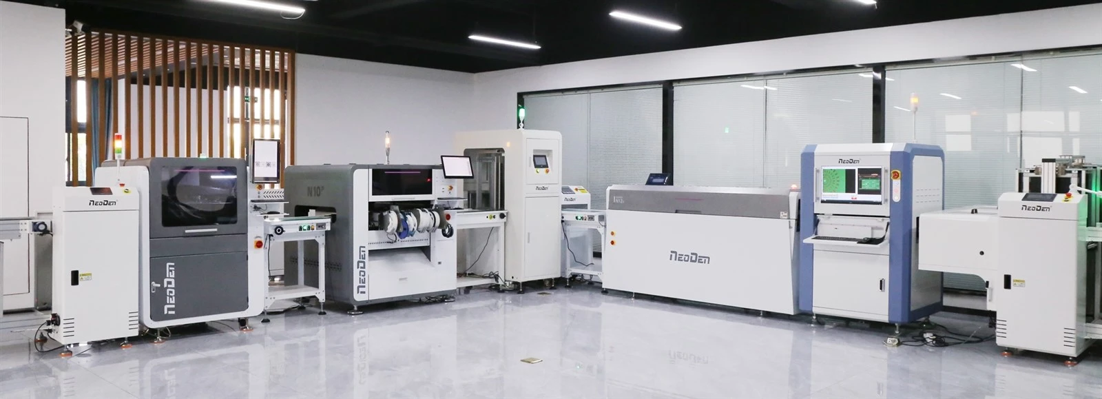
- Fully Automated In-Line SMT Production Line: A continuous assembly line formed by linking a screen printer, placement machine, reflow oven, and in-line AOI via automated conveyors. Suitable for high-volume manufacturing, it significantly reduces labor costs and the risk of misalignment caused by manual handling.
For high-density, multi-shift production needs, equipment such as the NeoDen9 and NeoDen N10P are equipped with multi-placement head configurations, continuous placement logic, and feeder status monitoring capabilities.
7 Common Misconceptions When Purchasing SMT Placement Machines
- Focusing solely on the nominal maximum CPH: This overlooks the actual speed reduction and board-feeding cycles that occur when vision alignment is enabled.
- Underestimating feeder station requirements: Purchasing too few feeder stations results in frequent disassembly and reassembly of feeders when switching between different products.
- Ignoring component height and package restrictions: Discovering after purchase that the equipment cannot accommodate tall capacitors, heavy inductors, or large IC trays.
- Ignoring PCB dimensions and board rigidity: Failing to verify the maximum track width or overlooking the sagging of thin boards when unsupported.
- Assuming machine accuracy can mask process defects: Placement offset is sometimes not a mechanical accuracy issue, but rather caused by defective printing stencils, worn nozzles, or non-standard mark point design.
- Neglecting programming and file compatibility: Selecting equipment with proprietary software makes importing standard CAD coordinate files extremely cumbersome.
- Neglecting after-sales support and spare parts supply: Overlooking the daily maintenance costs and technical support required for consumables such as camera lenses, nozzles, vacuum tubes, and guide rails.
FAQ
Q1. What is the single most critical factor when selecting a SMT machine?
A. Production compatibility. The equipment must fully support your component package range, PCB dimensions, BOM material types, and target production capacity-rather than simply pursuing a single metric.
Q2. Does a SMT placement machine really need to be equipped with a vision system?
A. Yes. Equipment without vision systems operates solely based on stepper motor steps. If components in the tape are even slightly misaligned or the PCB is positioned at a slight angle, the absence of vision-based correction will result in extremely high defect rates for misplacement, solder bridging, and cold solder joints.
Q3. How can you accurately calculate the required number of feeder stations?
A. Identify the PCB with the most component varieties in your current BOM. Calculate the number of 8mm, 12mm, and 16mm tape reels required for that PCB, as well as the number of components in tubes and trays. We recommend selecting a machine with a feeder count slightly greater than the maximum number of components in a single PCB's BOM, so that frequently used components can be kept loaded, thereby reducing changeover effort.
Q4. What is the difference between desktop-class SMT machines and medium- to high-speed in-line SMT machines?
A. Desktop-class machines (such as the NeoDen4) feature a compact design and support manual or semi-automatic board feeding, making them ideal for R&D prototyping and small-batch production. In contrast, medium- to high-speed in-line machines (such as the NeoDen9 / N10P) utilize a heavier-duty frame, a multi-head gantry structure, and fully automated tracks, and are specifically designed for continuous, automated assembly line operations.
Conclusion
Selecting the right SMT machine requires precisely matching the equipment's capabilities to actual production needs. We recommend following this 5-step decision-making process:
Step 1: Determine PCB dimensions and panelization design
Step 2: Identify the range of component packages and heights in the BOM
Step 3: Assess actual monthly production capacity targets
Step 4: Verify feeder capacity, vision system configuration, and nozzle ecosystem
Step 5: Comprehensively evaluate total cost of ownership (TCO) and after-sales technical support
Get Customized Selection Recommendations
If you're unsure which NeoDen pick and place machine configuration best suits your PCB design and production capacity plans, please provide your PCB dimensions, BOM component list, and target output to our technical team. We'll customize the equipment and feeder configuration that best meets your production efficiency needs.